
Process island: Surface Treatment
Yes. Type II anodizing typically adds about 10–15 µm to the diameter of an aluminum shaft. On a Ø20 shaft, the g6 tolerance band is only 13 µm wide, so the coating growth alone is about as large as the whole band. For a fit diameter that will be anodized, specify g8 and remove the envelope requirement (Ⓔ). g8 has the same upper limit as g6, so the fit is never tighter than before. The extra width is all on the lower side, where it absorbs coating variation and makes the part producible in volume. The trade-off is a larger maximum clearance, about 20 µm more on Ø20; check that the fit still works at that clearance.
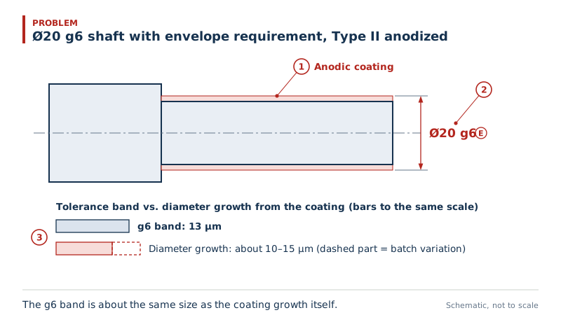
Why it happens
- Coating growth varies from batch to batch, and the turned diameter varies too. Both have to fit inside the same 13 µm band, which production cannot hold reliably.
- The envelope requirement (Ⓔ) means the whole length of the fit diameter must stay inside the maximum-material boundary. Uneven coating makes that check stricter still.
- The result is parts rejected after anodizing. Reworking them means stripping the coating, and stripping also removes base material.
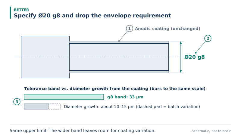
When this applies
- Aluminum shafts with Type II anodizing on a fit diameter specified as g6 or similarly tight.
- If the function really needs g6, plan a different process route, grinding plus Type III hard anodizing (see "How tight a tolerance can I hold after anodizing?"), instead of forcing it through a standard anodizing process.
- State on the drawing that the dimension applies after treatment.
Basis for the numbers
- Ø20 falls in the 18–30 mm range: IT6 = 13 µm, IT8 = 33 µm; the fundamental deviation for g is es = −7 µm at every IT grade. Source: ISO 286-2, shaft tolerance tables.
- Increase in maximum clearance: IT8 − IT6 = 20 µm for the 18–30 mm range (ISO 286-2).
- Envelope requirement (Ⓔ): ISO 14405-1.
- Diameter growth of about 10–15 µm from Type II anodizing: general shop experience. Actual values depend on the specified coating thickness and the anodizer.
- Ø20 is an illustrative example size.
Other ways engineers ask this
- Will my aluminum shaft get bigger after anodizing, and will the fit get tighter? Yes, by about 10–15 µm on diameter with Type II anodizing. Whether the fit gets tighter depends on whether the drawing tolerance leaves room for that growth.
- Can I hold g6 on an anodized shaft? Not reliably with standard Type II anodizing. It takes a grinding and hard-anodizing route.
- Is the shaft diameter on the drawing before or after anodizing? Say so on the drawing. For a fit diameter, specify the size after treatment.
AnvilQ gives design engineers manufacturability feedback on machined parts, so questions like this come up before the drawing goes out for quotation.
Get started